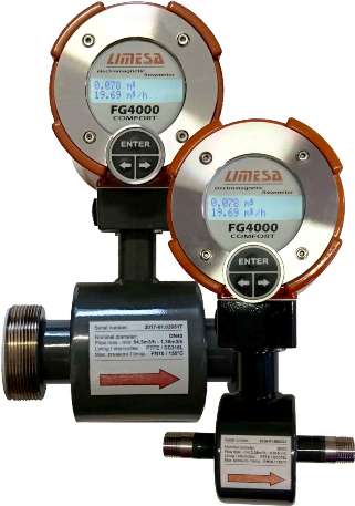
These electromagnetic flow meters with G sensors are mounted into a pipeline by means a standard G pipe outer thread (BSPP ISO 228 / DIN 259). They are mounted in pipes using G (gas) threads. They are primarily designed for a modernization of an existing installations, where an old mechanical water meters are still used. Their built-in lengths are based on a same ISO lengths as the mechanical water meters have. Due to this, the replacing of current outdated water meter with a modern electromagnetic flow meter is really simple and quick. No changes of an existing pipeline. Just replacing of the old one with the new one.
The sensor covers could be made from a standard carbon steel with an epoxy painting finishing. Optionally it can be made from a stainless steel SS304 or SS316L. The stainless steel finishing meets better hygienic requirements and requirements to operate in aggressive and humid environments. For operations with particularly aggressive influences (high relative humidity, acidic or alkaline environment, high / low temperatures, …), these sensors can be delivered in a separate design. In this case the transducer (flow meter display unit) is connected to the sensor with a shielded cable up to 40 m long, then it may be located outside of these areas. Separate sensor design can be optionally made with IP68 protection.
These “G” flow tubes are only made with PTFE (Teflon) liner, with a choice of several sensing electrode materials (316L stainless steel, Hastelloy C, titanium, tantalum,…).
These sensors can be used to measure the flow of drinking water, wine products, fruit juices, milk, whey, beer and other, too. The stainless sensors also resists cleaning lye and acids that are used daily in these industries. The PTFE liner and the flow meter itself meet hygienic requirements according to Act No. 258/200 Coll. and Decree of Ministry of Health No. 409/2005 Coll. to products coming into constant contact with drinking and hot water. The PTFE liner and SS316L electrodes complies with the EU regulation EC No 1935/2004.
The basic dimensions and built-in lengths are based on the ISO standards (See table below). Other nonstandard built-in lengths, dimensions or thread connection can be supplied according to order specification. Please contact our sales department.
| Transducer: | COMFORT | ECONOMIC |
| Display: | YES (2x16 chars) | NO |
| Keypad: | YES | NO |
| Measuring range: | 1 :40 ( ±0,5% for MPE standard); 1:500 (Q0=0,2% Qmax) | |
| Accuracy: | ± 0.5 % (± 0.003 m/s) in range from Qmin do Qmax | |
| Minimum liquid conductivity: | >5ųS/cm – common liquids; ≥20ųS/cm – demineralized water | |
| Power supply: | 230 VAC (+10;−15%) 50–60Hz; optionally 120VAC, 24VAC, 24VDC | |
| Power demand: | 10 VA | |
| IEC 536 protection class: | I | |
| Ingress protection rating: | IP67 | |
| Meter finish: | powder paint (RAL 8023) | |
| Ambient temperature rangé: | 0–70°C; recommended 15–55°C | |
| Pulse output 1: | in range 0.0001–1600 p/dm3 (maximum value depends on flowtube inner diameter) | |
| Pulse output 2: | state – signalization of the negative flow; pulse – negative volume (bidirectional flow) | |
| Pulse inputs: | 2× range (0.0001–1000 p/dm3) to display flow and/or volume measured by external | |
| Empty pipeline indication: | yes (optional) | |
| Communication modules: | RS485, RS422, RS232, M-Bus, ... (optional) | |
| Communication protocols: | SIMPLE, ModBUS, BitBUS, ASCII , MBUS | |
| Analogue outputs: | 4-20 mA, 0-10 V (optional) | |
| Archive: | hourly, daily, monthly, errors,.. (optional) | |
| DN - nominal diameter: | DN10 - DN65 |
| Thread: | G 1/2" - 3" BSPP ISO 228 (DIN 259) |
| Liner: | PTFE (teflon) |
| Electrodes: | Stainless steel SS316L (1.4571); hastelloy C; platina; tantal; titan |
| Nominal pressure: | PN16 |
| Floutube design: | Compact; separate – 4m cable (optionally ut to 40m) |
| Floutube finish: | Epoxy painting; SS304 or SS316L (polished stainless steel) |
| Ingres protection rating: | IP67 (optionally IP68) |
| Temperature of the measured liquid: | 0-150 °C (PTFE) |
| FG 4000 | „G“ flowtubes with G (BSPP) pipe thread | ||||||
| Thread [inches] | 1" (1/2") | 1" | 1 1/4" | 1 1/2" | 2" | 2 1/2" | 3" |
| DN [mm] | 10 | 15 | 20 | 25 | 32 | 40 | 50 |
| Q0 (m3/h) | 0,01 | 0,02 | 0,03 | 0,04 | 0,07 | 0,11 | 0,17 |
| Q1 (m3/h) | 0,08 | 0,19 | 0,34 | 0,53 | 0,87 | 1,36 | 2,12 |
| Q3 (m3/h) | 3,39 | 7,63 | 13,6 | 21,2 | 34,7 | 54,3 | 84,8 |
| k(Imp/dm3) | 1600 | 700 | 400 | 200 | 150 | 100 | 60 |
Threading – Dimension of the G thread
DN – Flowtube nominal inner diameter
Q0 – Starting flow
Q1 – Minimal flow
Q3 – Maximal flow
k – Maximal pulse constant of flow conversion
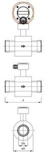
| G (BSPP) thread | DN | PN | A | ∅D | m[kg] |
|---|---|---|---|---|---|
| 1" (1/2") | 10 | 16 | 150 | 95 | 4,5 |
| 1" | 15 | 16 | 150 | 95 | 5 |
| 1 1/4" | 20 | 16 | 200 | 95 | 6,5 |
| 1 1/2" | 25 | 16 | 200 | 105 | 6,5 |
| 2" | 32 | 16 | 200 | 112 | 7 |
| 2 1/2" | 40 | 16 | 200 | 112 | 7 |
| 3" | 50 | 16 | 200 | 112 | 8,5 |
G (BSPP) thread – Dimension of the thread according to ISO 228 (DIN 259)
DN – Nominal inner diameter of the sensor
PN – Maximum allowable pressure
A – Length of the sensor
∅D – Outside diameter of the sensor cover
m – Sensor weight