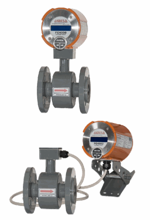
The flange flow sensor is the most commonly used design. These sensors can be fitted by a rubber or PTFE (teflon) liner. Possible material of sensing electrode is 316L grade stainless steel, Hastelloy C, titanium, tantalum,… this can be helpful to match every application requirements.
Basic rubber liner is recommended for a flow measuring of a most common liquids such as waste water, irrigation water, rain water, slurry, cooling purposes and many other liquids based on water in various industrial processes.
Teflon liner provide high chemical and thermal resistance as well as health safety. They are thus suitable for applications in chemical, dairy, food processing and other industries with similar requirements. The are commonly used to measure flow in drinking water, wine and related products, syrup, milk, whey, beer, and other food consumables. Besides other, they resist cleaning lyes or acids that are used in such applications on a daily basis.
The basic dimensions and flowtube built-in length comply with ISO standards (see the chart below). However, custom specified designs with other types of flanges (ANSI, BS, JIS, …) and custom built-in lengths may be supplied.
Our flanged flowtubes are provided with an earthing electrode in factory while earthing rings can be included on request. This guarantees flawless flow meter operation at all times even for installations in plastic pipework.
We further provide our flow meters with custom specified installation sets. Custom installation lengths and connections (DIN 11851 aseptic threading for food industry, DIN 32676 clamp, G gas threading etc.) may be specified.
Do you need offer or more information? Just ask our sales department, please.
| Transducer: | COMFORT | ECONOMIC |
| Display: | YES (2x16 chars) | NO |
| Keypad: | YES | NO |
| Measuring range: | 1 :40 ( ±0,5% for MPE standard); 1:500 (Q0=0,2% Qmax) | |
| Accuracy: | ± 0.5 % (± 0.003 m/s) in range from Qmin do Qmax | |
| Minimum liquid conductivity: | >5ųS/cm – common liquids; ≥20ųS/cm – demineralized water | |
| Power supply: | 230 VAC (+10;−15%) 50–60Hz; optionally 120VAC, 24VAC, 24VDC | |
| Power demand: | 10 VA | |
| IEC 536 protection class: | I | |
| Ingress protection rating: | IP67 | |
| Meter finish: | powder paint (RAL 8023) | |
| Ambient temperature rangé: | 0–70°C; recommended 15–55°C | |
| Pulse output 1: | in range 0.0001–1600 p/dm3 (maximum value depends on flowtube inner diameter) | |
| Pulse output 2: | state – signalization of the negative flow; pulse – negative volume (bidirectional flow) | |
| Pulse inputs: | 2× range (0.0001–1000 p/dm3) to display flow and/or volume measured by external | |
| Empty pipeline indication: | yes (optional) | |
| Communication modules: | RS485, RS422, RS232, M-Bus, ... (optional) | |
| Communication protocols: | SIMPLE, ModBUS, BitBUS, ASCII , MBUS | |
| Analogue outputs: | 4-20 mA, 0-10 V (optional) | |
| Archive: | hourly, daily, monthly, errors,.. (optional) | |
| Flowtube nominal inner diameter: | DN25 – DN600 (rubber); DN10 – DN350 (PTFE - teflon); DN300 - DN600 (E-CTFE) |
| Flowtube liner: | hard or soft rubber / PTFE / E-CTFE |
| Electrodes: | 316L grade (1.4571) stainless steel; Hastelloy C; platinum; tantalum; titanium |
| Nominal pressure: | DIN, EN1092 - PN10, PN16, PN25, PN40; ANSI - 150lb, 300lb |
| Flowtube design: | compact; split – 4m cabling (optionally up to 40m) |
| Temperature of the measured liquid | 0-150°C (PTFE); 0-90°C (rubber) |
| Flowtube finish: | epoxy paint (RAL 7043) |
| Ingress protection rating: | IP67 (IP68 optional) |
| FG 4000 | Flanged flow tubes “F” with hard rubber liners | |||||||||||||||||||
| Flanged flow tubes “F” with Teflon (PTFE) liners | ||||||||||||||||||||
| DN | 10 | 15 | 20 | 25 | 32 | 40 | 50 | 65 | 80 | 100 | 125 | 150 | 200 | 250 | 300 | 350 | 400 | 450 | 500 | 600 |
| Q0 (m3/h) | 0,01 | 0,02 | 0,03 | 0,04 | 0,07 | 0,11 | 0,17 | 0,29 | 0,43 | 0,68 | 1,06 | 1,53 | 2,7 | 4,2 | 6,1 | 8,3 | 10,9 | 13,7 | 17,0 | 24,4 |
| Q1 (m3/h) | 0,08 | 0,19 | 0,34 | 0,53 | 0,87 | 1,36 | 2,12 | 3,58 | 5,43 | 8,48 | 13,2 | 19,1 | 34,0 | 53,0 | 76,0 | 104 | 136 | 172 | 212 | 305 |
| Q3 (m3/h) | 3,39 | 7,63 | 13,6 | 21,2 | 34,7 | 54,3 | 84,8 | 143 | 217 | 339 | 530 | 763 | 1360 | 2120 | 3050 | 4160 | 5431 | 6867 | 8480 | 12200 |
| k(Imp/dm3) | 1600 | 700 | 400 | 200 | 150 | 100 | 60 | 35 | 25 | 15 | 10 | 7 | 4 | 2,5 | 1,6 | 1,25 | 1 | 0,75 | 0,5 | 0,4 |
DN– Flowtube nominal inner diameter
Q0– Starting flow
Q1– Minimal flow
Q3– Maximal flow
k– Max. constant of flow conversion
The table corresponds to the version with DIN flanges EN1092. Dimensions for ANSI flanges and others on request.
*DN10 – DN40 dimensions in parentheses are valid for a sensors with installed empty pipe detection.
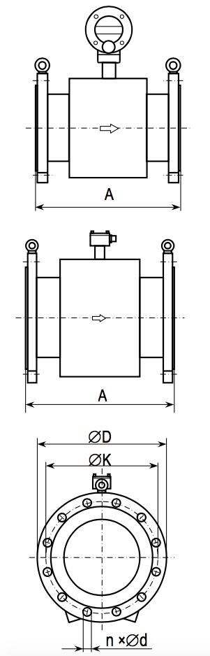
| DN | PN [bar] | A [mm] | ∅D [mm] | ∅K [mm] | n [pcs] | ∅d [mm] | m [kg] |
|---|---|---|---|---|---|---|---|
| 10 | 10, 16, 40 | 150 (200*) | 90 | 60 | 4 | 14 | 4,5 |
| 15 | 10, 16, 40 | 150 (200*) | 95 | 65 | 4 | 14 | 5 |
| 20 | 10, 16, 40 | 150 (200*) | 105 | 75 | 4 | 14 | 6,5 |
| 25 | 10, 16, 40 | 150 (200*) | 115 | 85 | 4 | 14 | 6,5 |
| 32 | 10, 16, 40 | 150 (200*) | 140 | 100 | 4 | 18 | 7 |
| 40 | 10, 16, 40 | 150 (200*) | 150 | 110 | 4 | 18 | 7 |
| 50 | 10, 16, 40 | 200 | 165 | 125 | 4 | 18 | 8,5 |
| 65 | 10, 16 | 200 | 185 | 145 | 4 | 18 | 12 |
| 40 | 200 | 185 | 145 | 4 | 18 | 12,5 | |
| 80 | 10, 16 | 200 | 200 | 160 | 8 | 18 | 12,5 |
| 40 | 200 | 200 | 160 | 8 | 18 | 13 | |
| 100 | 10, 16 | 250 | 220 | 180 | 8 | 18 | 14 |
| 40 | 250 | 235 | 180 | 8 | 22 | 16 | |
| 125 | 10, 16 | 250 | 245 | 210 | 8 | 18 | 19 |
| 40 | 250 | 270 | 220 | 8 | 26 | 21 | |
| 150 | 10, 16 | 300 | 285 | 240 | 8 | 22 | 23 |
| 40 | 300 | 300 | 250 | 8 | 26 | 27 | |
| 200 | 10 | 350 | 340 | 295 | 8 | 22 | 39 |
| 16 | 400 | 340 | 295 | 12 | 22 | 39 | |
| 250 | 10 | 400 | 395 | 350 | 12 | 22 | 50 |
| 16 | 400 | 405 | 355 | 12 | 26 | 55 | |
| 300 | 10 | 500 | 445 | 400 | 12 | 22 | 68 |
| 16 | 500 | 460 | 410 | 12 | 26 | 73 | |
| 350 | 10 | 500 | 505 | 460 | 16 | 22 | 95 |
| 16 | 500 | 520 | 470 | 16 | 26 | 110 | |
| 400 | 10 | 600 | 565 | 515 | 16 | 26 | 115 |
| 16 | 600 | 580 | 525 | 16 | 30 | 140 | |
| 450 | 10 | 600 | 615 | 565 | 20 | 26 | 135 |
| 16 | 600 | 640 | 585 | 20 | 30 | 155 | |
| 500 | 10 | 600 | 670 | 620 | 20 | 27 | 135 |
| 16 | 600 | 710 | 650 | 20 | 33 | 180 | |
| 600 | 10 | 600 | 780 | 725 | 20 | 30 | 185 |
| 16 | 600 | 840 | 770 | 20 | 36 | 200 |