
The electromagnetic flow meters are primarily designed for a wide range of industrial applications. Flow is determined on the electromagnetic induction principle that allows measuring without any mechanical parts in the metering profile, which results in virtually no pressure drop.
The FG4000 flow meter is a highly reliably instrument that offers accurate flow measurement in liquids at long-term stability. Its further features is a wide flow range while maintaining measurement accuracy with fast response to flow fluctuations. An alphanumeric display and three membrane keys provide comfortable operation. Last but not least, accent is put on design user-friendliness, such as easy access to the connectors.
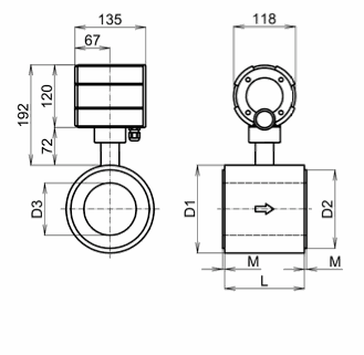
The flowmeter consists of two main parts, a measuring unit and a flow sensor (flow tube). The measuring unit is housed in a rigid aluminium casting that allows four positions of the flowtube in a horizontal or vertical pipe line while the correct operation position of the stainless steel front panel with display and membrane keys is always provided. The FG4000 flow meter advanced industrial design satisfies stringent requirements for mechanical as well as chemical resistance thus allowing to use the instrument under most rigorous conditions. The ingression rating of the flow meter is IP67 and resistance against electromagnetic interference in compliance with category E2 pursuant to EN ISO 4064-5 may be stressed. The measuring unit is also available as an ECONOMIC variant (without the display and keypad). This option is for applications where the flowmeter only serves as a flow and volume variable to the parent system.
The measuring unit allows you to connect a wide range of electromagnetic sensors from the most commonly used flanged, wafer, aseptic threaded, G threaded to customized design limited only by the dimensions given by the technical possibilities.
Integration of flowmeters into third-party extension systems, such as control, visualization and other systems, is enabled by standard pulse or analogue outputs. For a more sophisticated systems, the communication interface with open MeterBUS, RS485 (ModBUS, BitBUS, ASCII, simple), RS232 (ModBUS, Simple) protocols is determined.
The flowmeter can be equipped with empty pipe detection function. This additional function is recommended,when the permanent flooding of the sensor can not be met.
For more information, please contact our sales department.
| Transducer: | COMFORT | ECONOMIC |
| Display: | YES (2x16 chars) | NO |
| Keypad: | YES | NO |
| Measuring range: | 1 :40 ( ±0,5% for MPE standard); 1:500 (Q0=0,2% Qmax) | |
| Accuracy: | ± 0.5 % (± 0.003 m/s) in range from Qmin do Qmax | |
| Minimum liquid conductivity: | >5ųS/cm – common liquids; ≥20ųS/cm – demineralized water | |
| Power supply: | 230 VAC (+10;−15%) 50–60Hz; optionally 120VAC, 24VAC, 24VDC | |
| Power demand: | 10 VA | |
| IEC 536 protection class: | I | |
| Ingress protection rating: | IP67 | |
| Meter finish: | powder paint (RAL 8023) | |
| Ambient temperature rangé: | 0–70°C; recommended 15–55°C | |
| Pulse output 1: | in range 0.0001–1600 p/dm3 (maximum value depends on flowtube inner diameter) | |
| Pulse output 2: | state – signalization of the negative flow; pulse – negative volume (bidirectional flow) | |
| Pulse inputs: | 2× range (0.0001–1000 p/dm3) to display flow and/or volume measured by external | |
| Empty pipeline indication: | yes (optional) | |
| Communication modules: | RS485, RS422, RS232, M-Bus, ... (optional) | |
| Communication protocols: | SIMPLE, ModBUS, BitBUS, ASCII , MBUS | |
| Analogue outputs: | 4-20 mA, 0-10 V (optional) | |
| Archive: | hourly, daily, monthly, errors,.. (optional) | |
| Flowtube nominal inner diameter: | DN10 through DN600 |
| Flowtube design: | flange, wafer, DIN 11851 threading, DIN 32676 clamp, G threading,... |
| Flowtube connection: | compact; separate – 4m cabling (optionally up to 40m) |
| Flowtube liner: | hard or soft rubber; PTFE; ECTFE |
| Electrodes: | 316L grade (1.4571) stainless steel; Hastelloy C; platinum; tantalum; titanium |
| Nominal pressure: | DIN, EN1092 - PN10, PN16, PN25, PN40; ANSI - 150lb, 300lb |
| Temperature of the measured liquid: | 0-150 °C (PTFE); 0-90 °C (rubber) |
| Flowtube finish: | powder or epoxy paint (RAL 7043); brushed stainless steel |
| Ingress protection rating: | IP67 (IP68 optionally) |
(For dimensions of flow tubes see the current model of flow sensor)

| FG 4000 | Flanged flowtubes „F“ | |||||||||||||||||||
| Wafer flowtubes „W“ | ||||||||||||||||||||
| Wafer flowtubes – stainless steel „W-ss“ | ||||||||||||||||||||
| DN | 10 | 15 | 20 | 25 | 32 | 40 | 50 | 65 | 80 | 100 | 125 | 150 | 200 | 250 | 300 | 350 | 400 | 450 | 500 | 600 |
| Q0 (m3/h) | 0,01 | 0,02 | 0,03 | 0,04 | 0,07 | 0,11 | 0,17 | 0,29 | 0,43 | 0,68 | 1,06 | 1,53 | 2,7 | 4,2 | 6,1 | 8,3 | 10,9 | 13,7 | 17,0 | 24,4 |
| Q1 (m3/h) | 0,08 | 0,19 | 0,34 | 0,53 | 0,87 | 1,36 | 2,12 | 3,58 | 5,43 | 8,48 | 13,2 | 19,1 | 34,0 | 53,0 | 76,0 | 104 | 136 | 172 | 212 | 305 |
| Q3 (m3/h) | 3,39 | 7,63 | 13,6 | 21,2 | 34,7 | 54,3 | 84,8 | 143 | 217 | 339 | 530 | 763 | 1360 | 2120 | 3050 | 4160 | 5431 | 6867 | 8480 | 12200 |
| k(Imp/dm3) | 1600 | 700 | 400 | 200 | 150 | 100 | 60 | 35 | 25 | 15 | 10 | 7 | 4 | 2,5 | 1,6 | 1,25 | 1 | 0,75 | 0,5 | 0,4 |
DN– Flowtube nominal inner diameter
Q0– Starting flow
Q1– Minimal flow
Q3– Maximal flow
k– Maximal constant of flow conversion